PRODUCTS
LL9DTUE
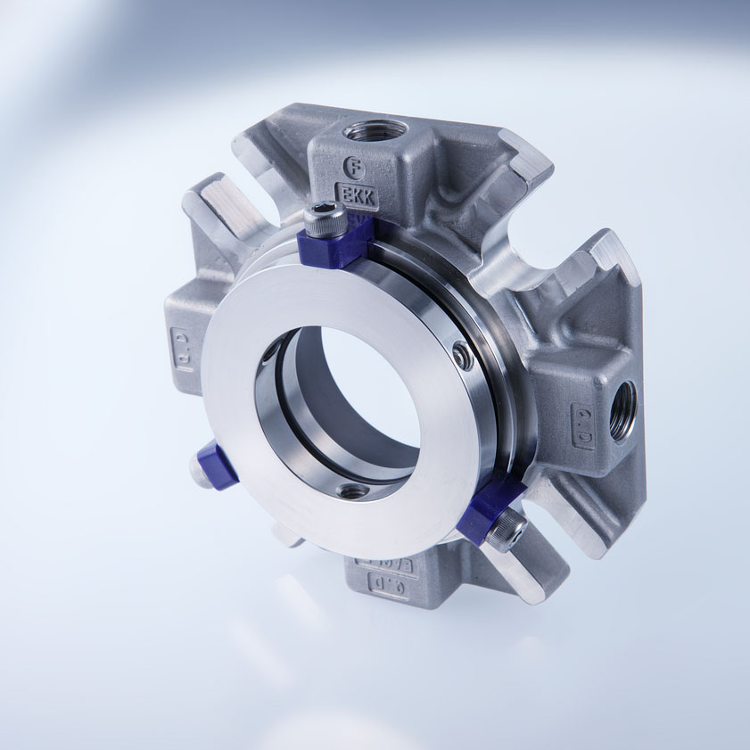
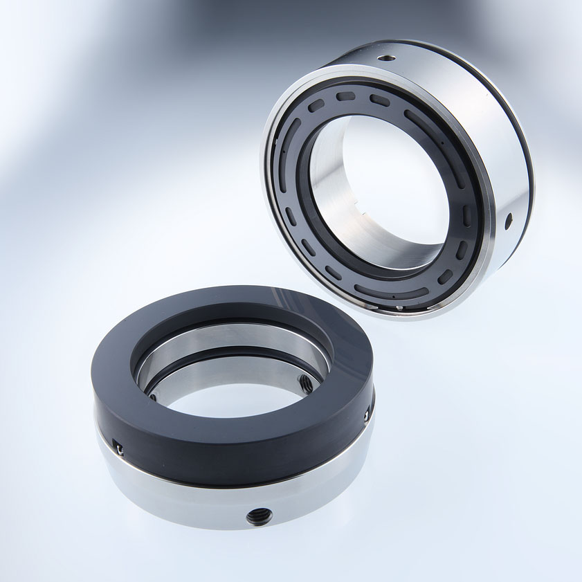
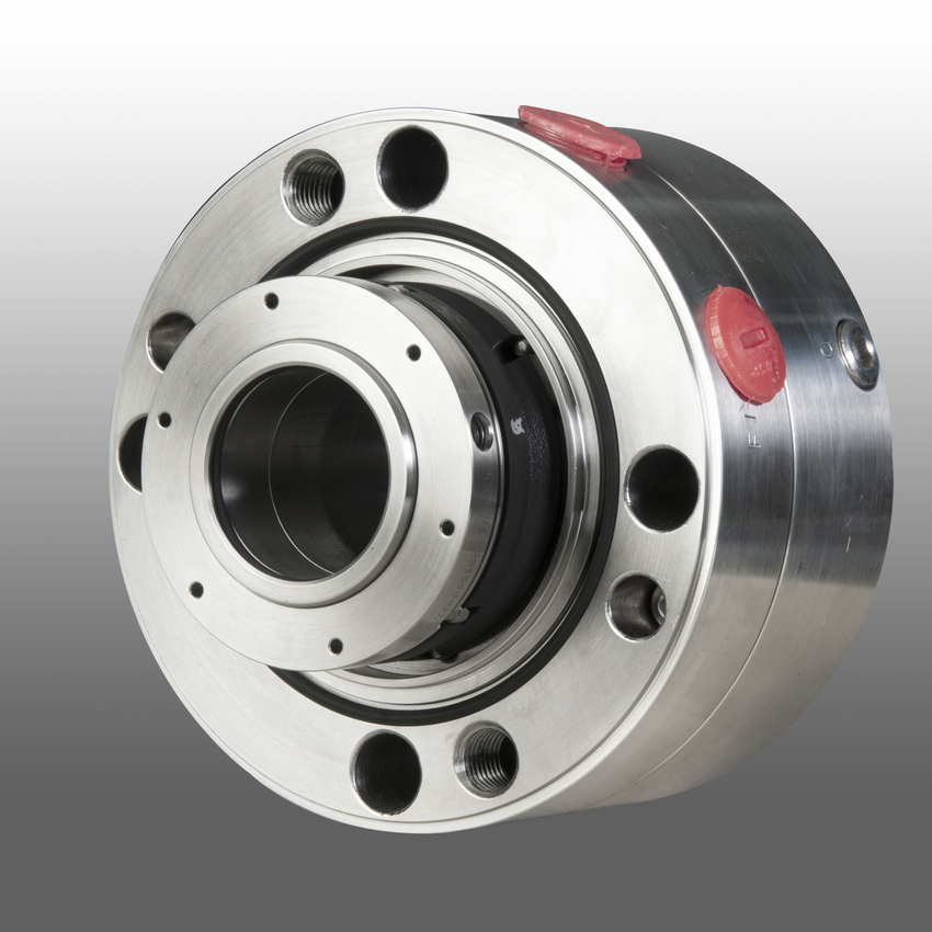
API Standard 682 seal
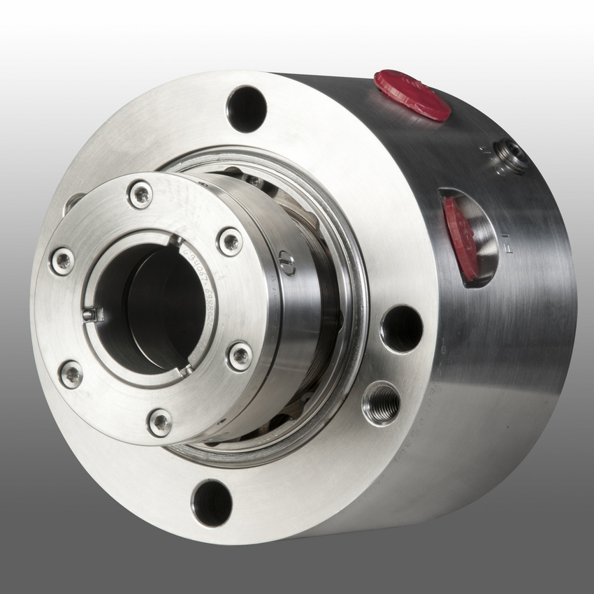
Mechanical seals for pumps
Pusher seals
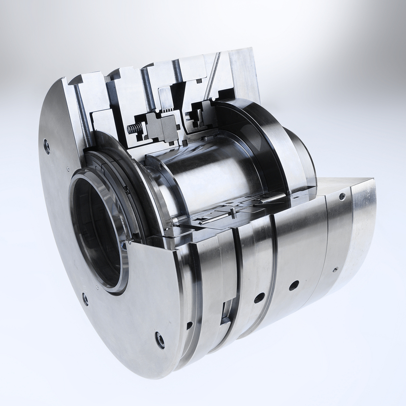
- Outer seal which can be used for flashing as well as non-flashing applications prevents hazardous emissions in case of inboard seal failure
- Low heat generation and power consumption due to narrow seal face width of inner seal
- Longer seal life
- Pressure-balanced design prevents mating ring being forced out under reverse pressure
- No damage to shaft sleeve as dynamic O-Ring is not in direct contact with the sleeve
Feature
Mechanical seals for pumps
Pusher seals
- API 682 Category 2 and 3, Type A, Arrangement 2 seal
- Dual seal in face-to-back arrangement
- Dry contact outer seal (containment seal)
- Balanced
- Cartridge unit
- Solid seal faces
Product specification example
Standards and approvals
API 682 / ISO 21049
Materials
Seal ring (primary seal): Blister resistant carbon, Silicon carbide SSiC (Q1), RBSiC (Q2)
Seal ring (secondary seal): Special carbon
Mating ring: Silicon carbide SSiC (Q1), RBSiC (Q2)
Secondary seals: FKM (V), FFKM (K), EPDM (E), NBR (P)
Springs: Hastelloy® C-276 (M5)
Metal parts: CrNiMo steel 316 (G)
Operating range
Pressure (primary Seal): p = vacuum … 42 bar (… 609 PSI)
Pressure (secondary seal): p = 2.75 bar (40 PSI) normal operation, max. 60 bar (870 PSI) in wet operation
Temperature: -40 °C … +176 °C (-40 °F … +349 °F)*
Sliding velocity: … 23 m/s (… 75 ft/s)
Viscosity: … 300 mPas
Solids content: … 0.5 wt.%
* Engineered up to 260 °C (500 °F) with FFKM (K) secondary seals
Recommended applications
Refining technology
Oil and gas industry
Petrochemical industry
Chemical industry
Power plant technology
Light volatile hydrocarbons
LPG plants API 610 / ISO 13709 pumps
Process pumps
Recommended piping plans
Process side: 02, 11, 12, 13, 14, 21, 22, 23, 31, 32, 41
Between seals: 71, 72, 75, 76
Applicable ranges, performance data and figures can serve only as a guide for selection and therefore in actual use there will be some cases where general specifications cannot be applied due to unknown factors or constraints.
Please check the applicability before use.
The contents are subject to change without notice for improvement.
Download Documentation